|
 |
Fibre Bragg Grating (FBG) Technology
Description
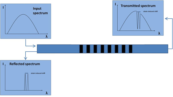
Fibre gratings are made by laterally exposing the core of a single-mode fibre to a periodic pattern of intense ultraviolet light. The exposure produces a permanent increase in the refractive index of the fibre's core, creating a fixed index modulation according to the exposure pattern. This fixed index modulation is called a grating. At each periodic refraction change a small amount of light is reflected. All the reflected light signals combine coherently to one large reflection at a particular wavelength when the grating period is approximately half the input light's wavelength. This is referred to as the Bragg condition, and the wavelength at which this reflection occurs is called the Bragg wavelength.
|
|
Light signals at wavelengths other than the Bragg wavelength, which are not phase matched, are essentially transparent. This principle is shown in Figure 1. Therefore, light propagates through the grating with negligible attenuation or signal variation. Only those wavelengths that satisfy the Bragg condition are affected and strongly backreflected. The ability to accurately preset and maintain the grating wavelength is a fundamental feature and advantage of fibre Bragg gratings. Gratings can also be designed to couple other phasematched wavelengths out of the fibre core, into radiation and cladding modes for tailoring of the grating spectrum.
|
|
|
|
Abb. 1-1: Working principle of the FBGs
|
|
|
FBG characteristics
The central wavelength of the reflected component satisfies the Bragg relation: ërefl=2 n Ë , with n the index of refraction and Ë the period of the index of refraction variation of the FBG. Due to the temperature and strain dependence of the parameters n and Ë, the wavelength of the reflected component will also change as function of temperature and/or strain, see Figure 2. This dependency is well known what allows determining the temperature or strain from the reflected FBG wavelength.
|
|
Besides temperature and strain, FBGs can be used to measure a variety of other physical parameters such as humidity, pressure, displacement, water leakage. This can be achieved using smart transduction mechanisms that convert the physical parameter into a strain value onto the FBG.
|
|
|
|
Abb. 1-2: FBG result as a function of strain
|
|
|
Multiplexing
The response of different FBG sensors can be monitored using only one optical fibre. This is achieved by putting different FBGs with different wavelengths in a series configuration, see Figure 3. Each reflected peak corresponds to a FBG. The wavelength responses of the different FBGs are recorded using a special designed fibre optic measurement system, operating in the band (1510 nm -1590 nm). The large wavelength window allows more sensors to be interrogated in a series configuration.
|
|
Interrogation principle
There are two fundamental approaches for monitoring the FBG responses:
-
The first approach makes use of a broadband light source that couples the light through a 2 by 2 coupler into the fibre where the FBGs will reflect different components.
This same coupler guides the reflected light, coming from the different FBGs, into an Optical Spectrum Analyser (OSA) module where the different peak wavelengths are calculated. If more then one sensing fibre is used, an additional optical switch is needed to make the interrogation of the different fibres possible.
-
In the second technique, a narrowband tunable laser is swept across the appropriate spectral region, and a reflected signal is observed with a broadband detector only when the laser is precisely tuned to the sensor’s reflectivity.
The control of the measurement system as well as the wavelength to temperature conversion is established using a graphical user interface that can be run from a laptop or desktop P.C.
|
|
|
|
| |
|
|